Files
Introduction
There are two multiple-geometry writing scenarios:
- Reading AND Writing multiple geometries
- Reading single geometry features and converting them to multiple geometries
If you are using FME 2025.2 or older, please refer to the relevant article.
Reading and Writing Multiple Geometries
In a Multiple -> Multiple translation, FME handles the reading and writing automatically.
In the Writer Feature Type, you can view the geometry columns automatically detected by the writer within the Geometry Definition Table.
Note: Keep in mind that if you change the geometry column names in the Geometry Definition Table, the incoming geometry name must match. The GeometryNameSetter transformer can be used to perform this task.
Reading Single and Writing Multiple Geometries
When converting single geometries to multiple, the key is in how to identify two features that are related, and how to assign each of them to the appropriate geometry column.
The GeometryNamerSetter can be used to differentiate your streams of data and provide them with unique geometry column names. In the example screenshot below, a CentrePointReplacer is used to create a center point for each record in the Parks dataset.
To ensure the data is written to a different column than the Polygon geometry, a GeometryNameSetter is used to assign it a unique geometry name. This is reflected in the writer feature type’s attributes.
Creating Tables with Multiple Geometry Columns
As of FME 2026.1, writers can now create tables with multiple geometry columns.
Current Supported Formats
As of FME 2026.1, the following formats support writing multiple geometry columns in FME. This list is expected to grow as support is added to more formats in the future.
- Microsoft SQL Server (JDBC MSSQL)
- Microsoft Azure SQL Database (JDBC MSSQL)
- Snowflake
- Microsoft SQL Server (MSSQL)
- Parquet & GeoParquet
- SAP HANA
- SAP HANA Cloud
- Teradata
Using Transformers to Manage Multiple Geometry Columns
Several FME transformers have the ability to manipulate and manage multiple geometry columns within your workspace, falling into two categories: those that manipulate geometry attributes on individual features, and those that combine geometries from multiple sources.
Manipulate Geometry Attributes
Combine Geometry Multiple Sources
Example of Using Transformers to Manage Multiple Geometry Columns
Example 1:Manipulating Geometry in a Multiple Geometry Column Workflow
In this example, a city parks dataset contains two geometry columns: “GEOM” (consisting of polygons) and “POINT” (consisting of points). Because the AreaCalculator requires polygon geometry, a GeometryRemover is first used to remove the “POINT” geometry column from the feature, allowing the AreaCalculator to calculate each park's area with the “GEOM” column.
A FeatureJoiner then re-joins the two data streams, ensuring both geometry columns are preserved as distinct columns. In the FeatureJoiner, the Geometry Handling parameter is set to “Keep Both (Preserve Distinct Geometries)”.
This is just one example of how geometry transformers can be used to handle multiple geometry columns in FME.
Example 2: Single Geometry to Multiple Geometry Workflow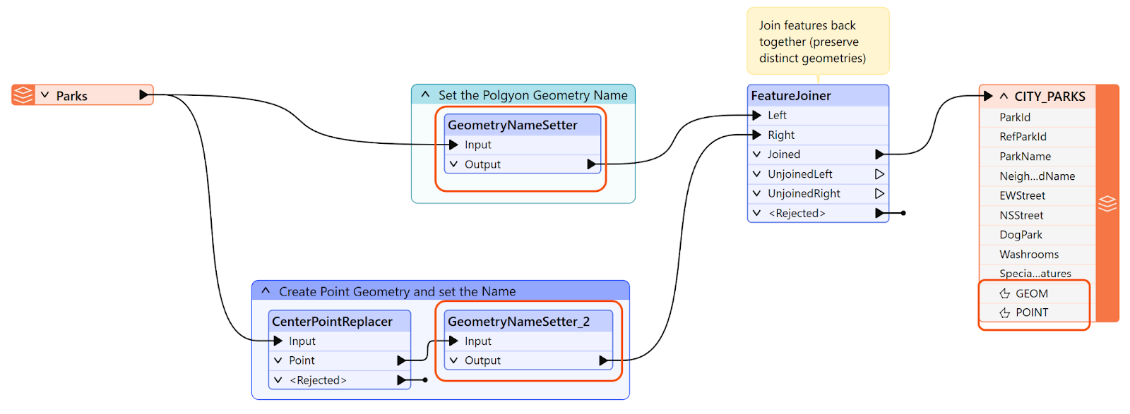
In this example, the CenterPointReplacer is used to generate a center point geometry from a parks dataset, resulting in two geometry columns that are then written to a database.
After using a GeometryNameSetter to assign a unique name to the new point geometry column, the two data streams must be joined back together before writing to the destination, otherwise duplicate rows will be written.
A FeatureJoiner accomplishes this, with its Geometry Handling parameter set to Keep Both (Preserve Distinct Geometries) to ensure both geometry columns are retained on the output feature.
As a result, each feature now contains two geometry columns - a polygon representing the original park boundary, and a point representing its centre point. The data can then be written to the destination database.