Introduction
Welcome to the Data Distribution Tutorial! This workspace allows users to extract and transform spatial data based on a defined area. It begins by capturing the user-defined area in GeoJSON format and reprojecting it to match the feature coordinate system. Next, it reads the selected feature layers that intersect with the defined area and clips these layers to the specified boundary. Finally, the workspace writes the clipped layers to the desired format and coordinate system using a generic writer.
Requirements
Before starting this guide, we highly recommend that you have completed at least one of the Getting Started with FME Form articles and familiarize yourself with published parameters.
Step-By-Step Instructions
From the Files section of this article, download the Transit.gdb file.
1. Open FME Workbench
Open FME Workbench and click on Blank Workspace on the Get Started page.
Alternatively, you can also click on File > New.
2. Create User Parameters
In this tutorial, you will create four user parameters. These parameters are designed to guide users and gather their input on their desired output.
Right-click on User Parameters in the Navigator pane, and click Manage User Parameters.
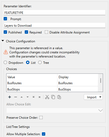
To create a new parameters, click the green plus sign in the top-left corner of the dialog and select the type of parameter. Then on the right-hand side of the dialog, fill in the following parameter details. The first parameter will prompt users to specify which layers they want to download from the database.
- Type: Choice
- Parameter Identifier: FEATURETYPE
- Prompt: Layers to Download
- Parameter: Published, Required
-
Choice configuration: List
- Choices: BusRoutes, BusStops, SkytrainStations, SkytrainLines
- Allow Multiple Selection: Enabled
- Default Value: <Leave Blank>
To create the next parameter, click on the green plus sign again and chose the type. The second parameter will allow users to select the area from which they want to download data. By creating a geometry user parameter type, users can display the specified coordinates on a map and define the desired geometry. Since the Transit database is in Vancouver, the initial bounds are set to that location. If you are unsure of your specific initial bounds, refer to the How to Determine Map Bounds with FME section.
- Type: Geometry
- Parameter Identifier: GEOM
- Prompt: Area of Interest
- Parameters: Published, Required, Disable Attribute Assignment
-
Geometry Configuration:
- Geometry Encoding: GEOJSON
- Geometry Types: Polygon Box
- Specify initial bounds for map displays: Enabled
- Top: 49.2548
- Left: -123.244
- Bottom: 49.3034
- Right:-123.071
- Default Value: <Leave Blank>

The third parameter allows users to select an output format for their data.
- Type: Choice
- Parameter Identifier: GENERIC_FORMAT
- Prompt: Output Format
- Parameter: Published, Required
-
Choice configuration: Dropdown
- Choices: ACAD, GML, OGCKML, PDF2D, SHAPEFILE, CSV2 - You can use Import from Reader Formats to quickly search for them as well.
- Allow Choice Edit: No
- Default Value: <Leave Blank>
The fourth parameter enables users to select the output coordinate system. Given that the Transit database covers the Vancouver region, we will restrict the coordinate system choices to those suitable for this area.
- Type: Choice
- Parameter Identifier: COORDSYS
- Prompt: Output Coordinate System
- Parameter: Published, Required
-
Choice Configuration: Dropdown
- Choices: BCALB-83, BCPOLY-83, EPSG:26910, EPSG:4326 - You can use Import from Coordinate Systems to quickly search for them as well
- Allow Choice Edit: No
-
Conditional Visibility:
- If Generic_Format Is Comma Separated Value (CSV)
- Then Hide
- Else Show As Enabled
- Default Value: <Leave Blank>
Conditional Visibility of workspace published parameters enables authors to determine under what condition(s) published parameters will be visible at runtime. This functionality allows authors to disable or hide published parameters that are not relevant to a particular translation based on the value selected for another user parameter. We want to set it up here so that when users choose a CSV format file, the Coordinate System parameter will be hidden, making the dialog less cluttered. You can read Working With Conditionally Visible Published User Parameters in FME Form for more information.
An important point to keep in mind about the new Conditional Visibility property is that the order of parameters in the Manage User Parameters dialog matters. More specifically, when one parameter’s visibility depends on the state or value of another parameter, the dependent parameter must reside below its related parameter in the Manage User Parameters dialog. Otherwise, the visibility condition set on the dependent parameter will no longer be valid, and its If…clause will appear red.
Click OK to save the four user parameters and to close the dialog.
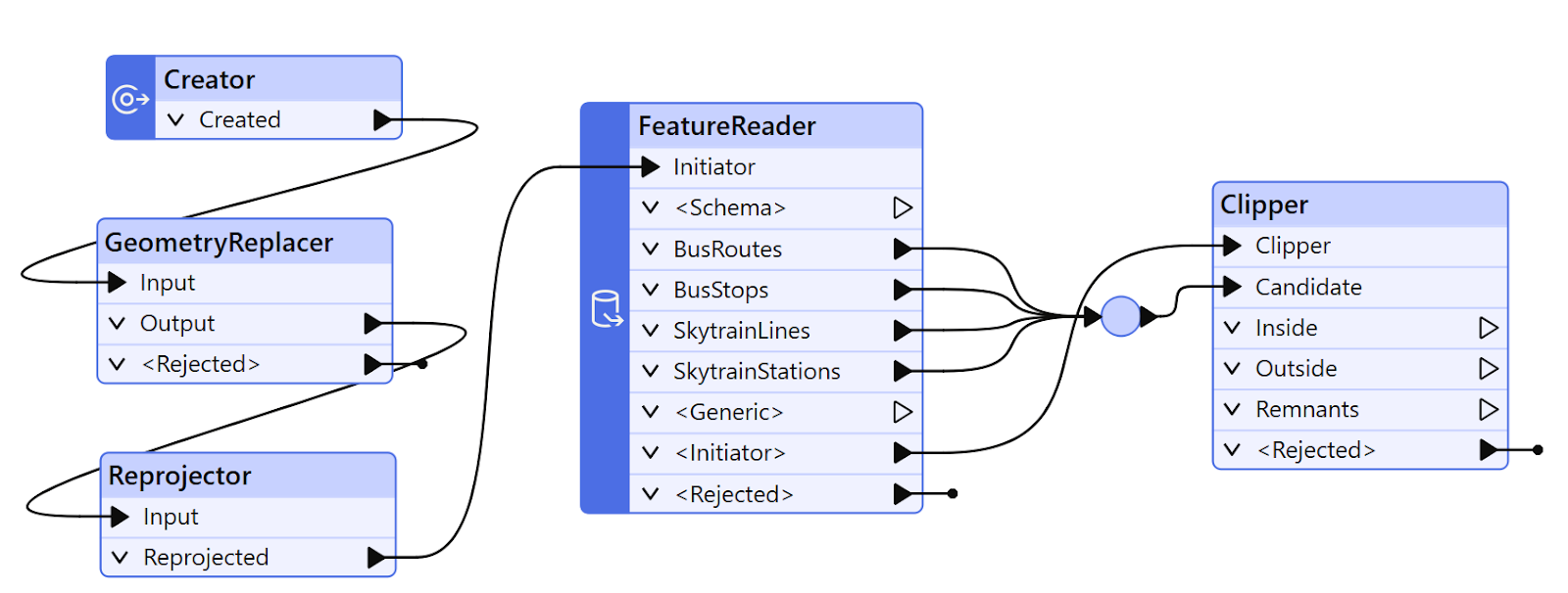
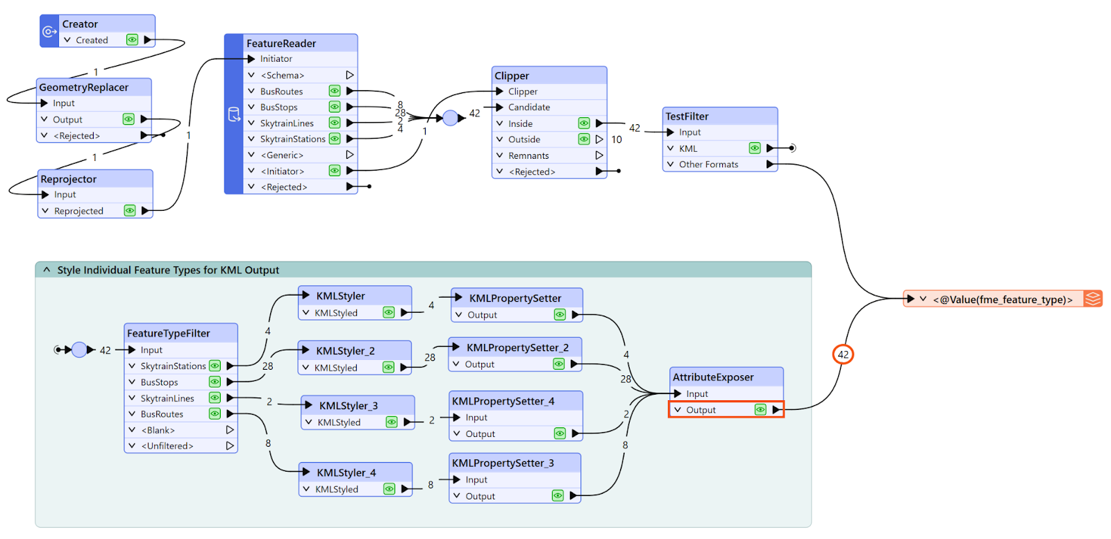
3. Add Creator and GeometryReplacer Transformers
Add a Creator transformer to your workspace using the default parameters. The Creator transformer generates an initial feature, which acts as a starting point for the workspace. Then, add a GeometryReplacer and connect the Creator transformer to it. The GeometryReplacer transformer takes the user-defined area and replaces the initial feature's geometry with this user-defined geometry.

4. Modify GeometryReplacer Parameters
Open the GeometryReplacer parameters. Set the Geometry Encoding to GeoJSON, set the Geometry Source to the GEOM user parameter, and then set Remove Attribute to No.
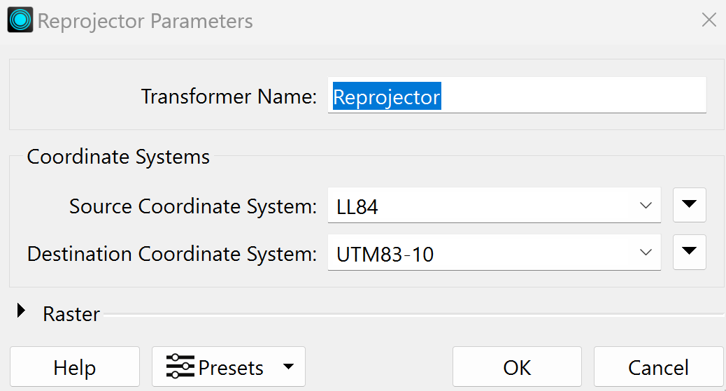
5. Add the Reprojector Transformer and Modify the Parameters
Since the Transit.gdb is in Vancouver, we need to ensure that the data is set in UTM83 Zone 10. To achieve this, add a Reprojector transformer to the canvas and connect it to the GeometryReplacer transformer.
In the Reprojector parameters, set the Source Coordinate System to LL84. We defined the initial bounds box in previous steps, and since the GeometryReplacer is connected to the Reprojector transformer, we know the coordinate system. Set the Destination Coordinate System to UTM83-10.
6. Add a Feature Reader Transformer and Modify the Parameters
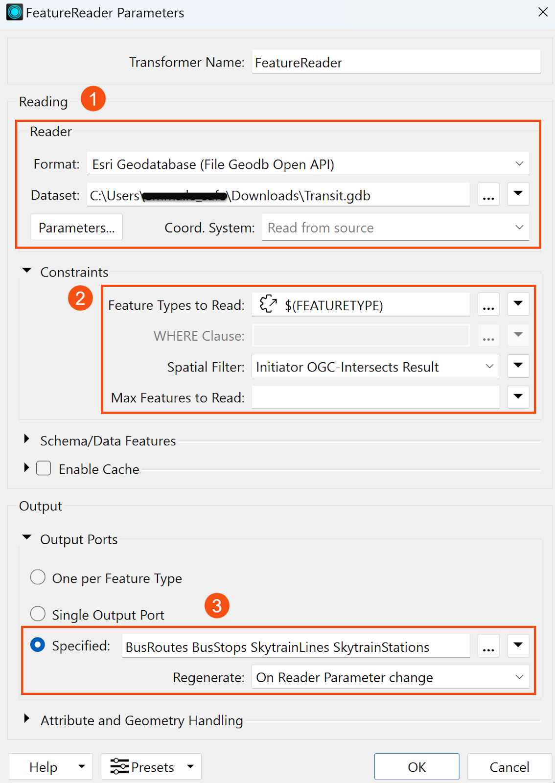
Add a FeatureReader transformer to read from the transit.gdb file.
In the parameters, set the format to Esri Geodatabase (File Geodb Open API) and select the transit.gdb file that you downloaded.
In the Constraints section, link the FEATURETYPE user parameter to the Feature Types to Read property. This ensures that the workspace only reads the features selected by users rather than all of them. For the Spatial Filter, set it as Initiator OGC-Intersects Result.
Finally, expand the Output Ports section, choose Specified, and add the four features by clicking the ellipsis. This assigns each feature its own output port.
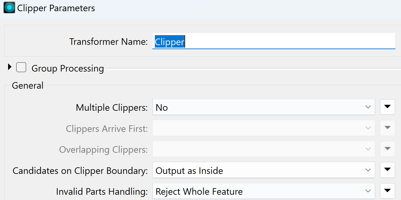
7. Add Clipper Transformer
Add a Clipper transformer to clip the feature layers to the region specified by users. Connect the <Initiator> port to the Clipper port, and connect the BusRoutes, BusStops, SkytrainLines, and SkytrainStations ports to the Candidate port.
In the Clipper parameters, set "No" for Multiple Clippers and leave the rest as default.
8. Add TestFilters
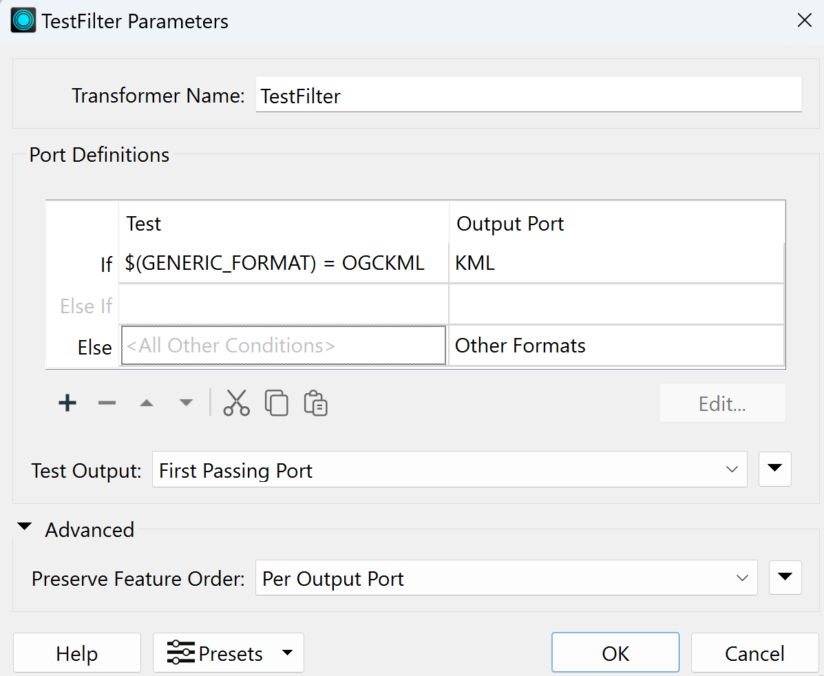
One of the objectives of this workspace is to allow users to select their preferred data format for the final output. Among these formats is OGCKML, for which we want to customize the appearance of the output file. To achieve this, add a TestFilter transformer and connect it to the Inside output port on the Clipper. Now we will create two output ports: one for KML data format and the other for all remaining formats. The KML output will undergo styling adjustments before the final output, while the other formats will be directly routed to a generic writer.
In the TestFilter parameters, set the Port Definitions as the following:
| Test | Output Port | |
| If | $(GENERIC_FORMAT) = OGCKML | KML |
| Else | Other Formats |
9. Add Styling for KML Output
We want to add styling for KML output to create an informative representation of the data and ensure the final result has the usability requirements for users interacting with KML format data.
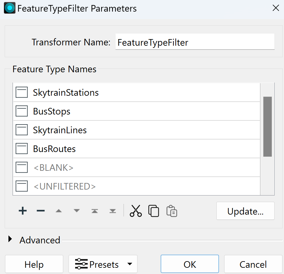
First, add a FeatureTypeFilter transformer to route features to different output ports, allowing for separate customization of each type. In the parameters, make sure to include all four main feature types:
- SkytrainStations
- BusStops
- SkytrainLines
- BusRoutes
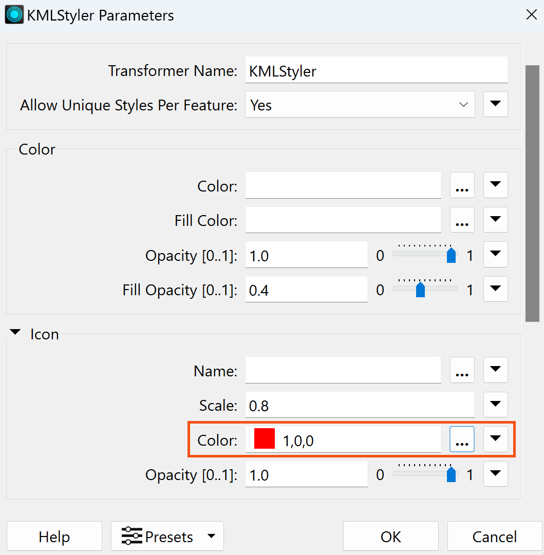
Next, add a KMLStyler transformer for each of the four feature types, four KMLStylers in total.
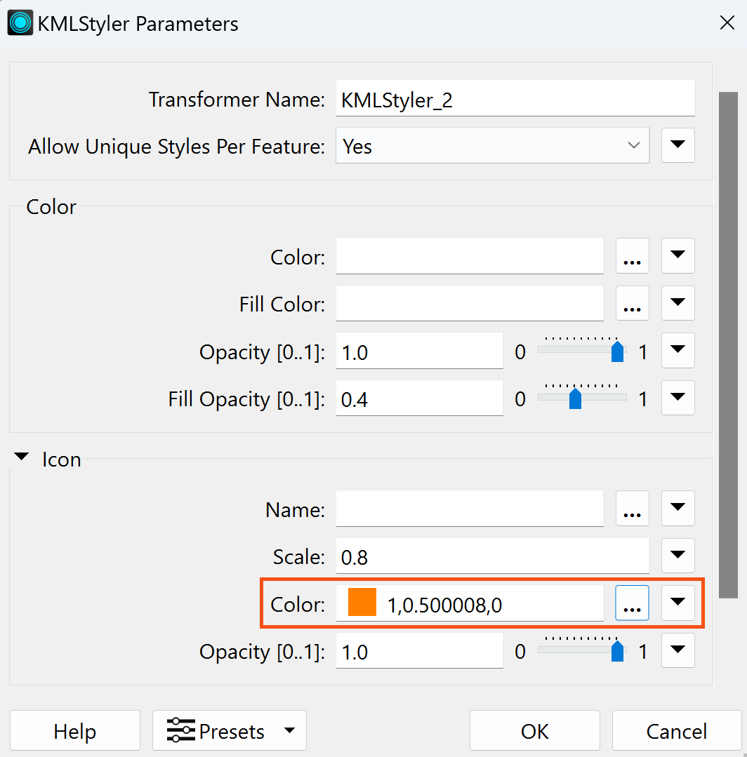
- SkytrainStations: These are point features; adding icons is ideal. In the KMLStyler Parameters, expand the Icon section and choose red or a color of your choice. Leave the other settings as default.
- BusStops feature type: Follow the same steps as for SkytrainStations, but select orange or any other color to differentiate them.
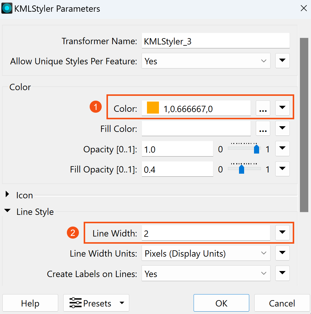
- SkytrainLines feature type: These are line features, so icons are unnecessary. Change the color in the Color section to orange or another color of your choice. Expand Line Style and set the Line Width to 2 for better visibility in Google Earth.
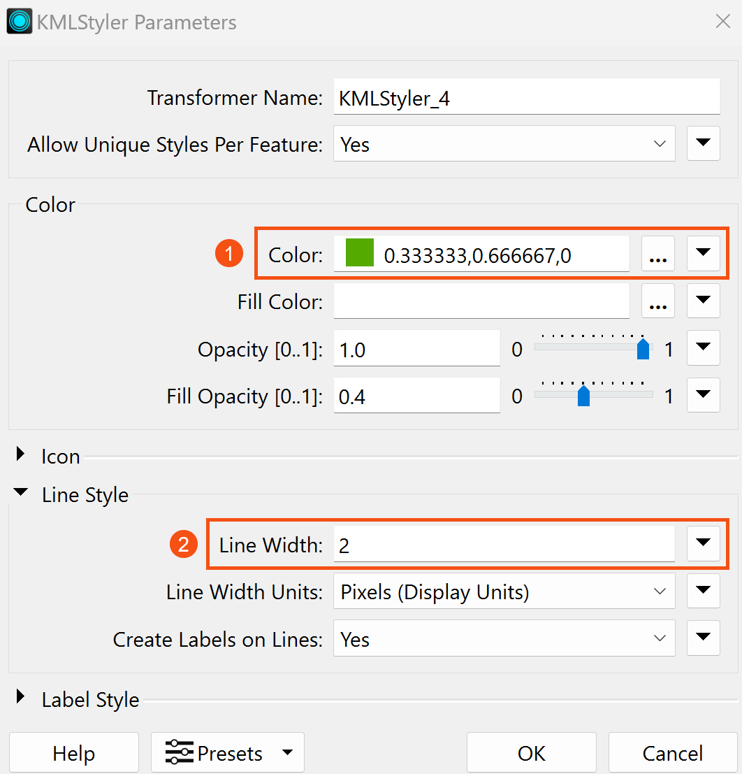
- BusRoutes feature type: Repeat the steps for SkytrainLines, but choose green or any other color as the color.
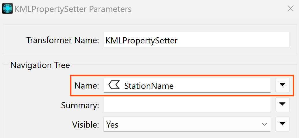
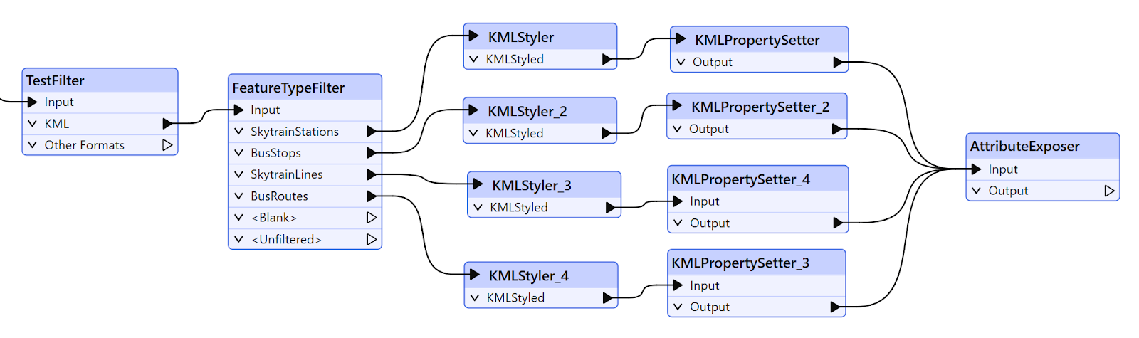
Finally, add a KMLPropertySetter transformer and connect it to each of the four KMLStyler transformers created in the previous steps, four in total. The KMLPropertySetter transformer ensures that the names of each feature type will appear in the output. For example, for the BusStops output, the stop number will be visible when added to Google Earth.
In the KMLPropertySetter parameters, modify only the attribute value for Name in the navigation tree. You can leave the other settings as default.
- SkytrainStations: StationName
- BusStops: StopNumber
- SkytrainLines: LineName
- BusRoutes: RouteName
Here’s an example of the KMLPropertySetter transformer for SkytrainStations
10. Expose Attributes
To access the unexposed fme_feature_type and fme_basename attributes, add an AttributeExposer transformer and connect it to all four of the KMLPropertySetters. In the parameters, select fme_feature_type and fme_basename as the attributes to expose. Ensure all four feature types are connected to this transformer. Your workspace should now look like this.
11. Add a Generic Writer
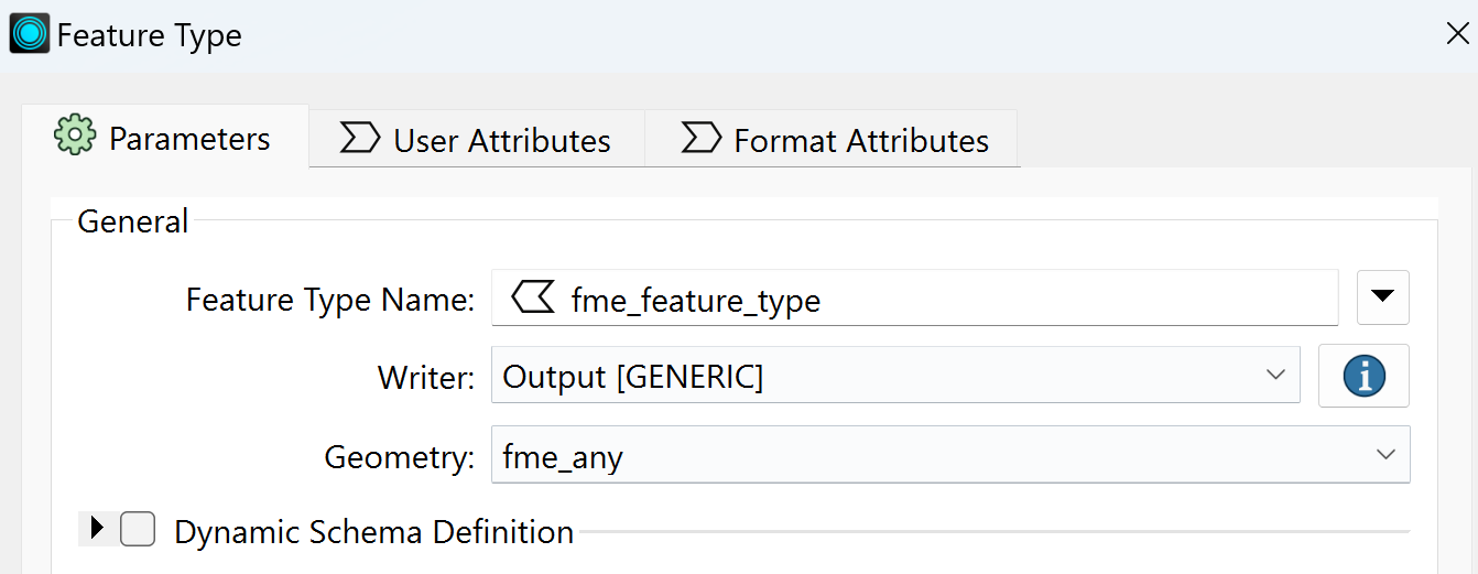
Add a Generic (Any Format) writer. In the parameters, set the Dataset to an output folder location of your choice. Next, click on Parameters, and change the Output Format to Generic (Any Format), then click OK twice to finish adding the writer.
In the Feature Type dialog that appears, click the drop-down next to Geometry and select fme_any. Then click OK, we will come back to these parameters in a moment. Connect the writer feature type to all of the KMLPropertySetters and the Other Formats output port on the TestFilter. To make your connections look nicer, you can add a Junction to connect to all four of the KMLPropertySetters and then connect the Junction to the writer feature type instead.
Double-click on the writer feature type to open the parameters again. Click on the drop-down arrow next to Feature Type Name, expand Attribute Value, and then click on fme_feature_type. This method is called Feature Type Fanout, which is a way to split output data based upon the value of an attribute. To learn more about Feature Type Fanout, see the Fanout | How to Separate Features Based on an Attribute article. Click OK to close the parameters.
12. Link to a Parameter
The final step before we can test the workspace is to connect the coordinate system and format user parameters. In the Navigator pane, expand the Output [GENERIC] writer and right-click on Coordinate System, then click Link to a Parameter. In the dialog, select the COORDSYS user parameter. This will provide users with access to the curated list of coordinate systems selected in the previous steps.
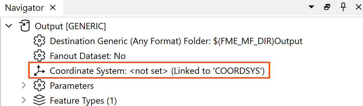
Next, expand Parameters, right-click on Output Format, and click Link to a Parameters. In the dialog, select GENERIC_PARAMETER. The gear icon will turn red in the Navigator; that is because an output format has not been selected yet. Now when we run the workspace, the user will be prompted to select an output format and coordinate system.
13. Test Workspace
Run the workspace with Prompt for Parameters enabled to test your workspace's functionality.

In the dialog, select a layer to download, then for Area of Interest copy and paste in the following:
{"type":"Polygon","coordinates":[[[-123.134079,49.276543],[-123.134079,49.287126],[-123.112278,49.287126],[-123.112278,49.276543],[-123.134079,49.276543]]]}.
If you would like to select different parameters every time the workspace is run, uncheck Save As Parameter Default values. Once ready, click Run.
Once the workspace finished running, check the Translation Log for any errors and check the destination folder to make sure you have the data translated correctly.
Congratulations, you have completed building a workspace for data distribution! If you want to publish the workspace to FME Flow, refer to the article Publish a Workspace to FME Flow and Run It. For a step-by-step guide on creating a workspace app using this data distribution workspace, follow the instructions in the FME Flow App Examples article.
Explore our FME Support Center for more tutorials, tips, and guidelines. Additionally, visit FME Academy to explore our comprehensive training catalog for a more in-depth study!
Data Attribution
The data used here originates from open data made available by the City of Vancouver, British Columbia. It contains information licensed under the Open Government License - Vancouver.